
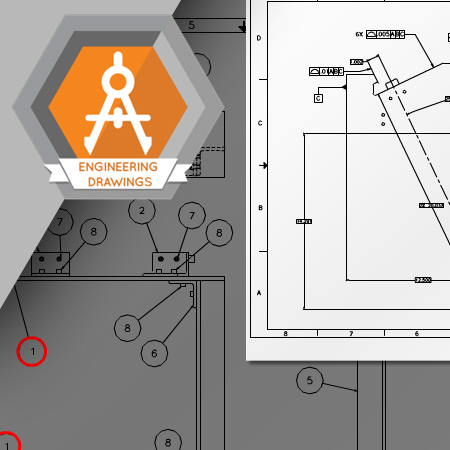
Engineering detail drawings communicate design intent along the entire supply and production line to ensure that mechanical parts meet a desired form, fit, and function.
Learning Objectives
- Understand the history of the Y14.5 standard
- Define the purpose of an engineering detail drawing
- Define the terms dimension, tolerance, and geometric tolerance
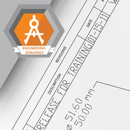
There are many terms and symbols unique to engineering drawings. Understanding these terms and symbols is important in understanding the design intent of the part represented on the drawing.
Learning Objectives
- Understand how different units of measure are represented on engineering drawings
- Define the symbols used on engineering drawings
- Identify the components of a dimension
- List locations of dimensions
- Define a reference dimension
- Define a basic dimension
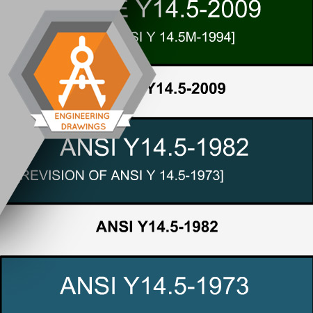
ASME Y14.5 requires engineering drawings to be created and interpreted to a set of rules. Understanding these rules is important to understanding the design intent of a part.
Learning Objectives
- Understand Rule #1 of GD&T
- List tolerance zone shapes
- Define size
- Define the local size of a feature of size
- Define actual mating size
- Understand the implied 90-degree rule
- Understand how to apply general, or block, tolerances
Engineers use geometric tolerances to convey the design intent of the form or location of features when size tolerances may be too restrictive.
Learning Objectives
- List the geometric characteristics controlled by geometric tolerances
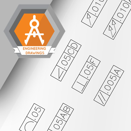
- Identify the symbols used in geometric tolerances
- Identify a feature control frame
- Identify the tolerance area of a feature control frame
- Identify the geometric characteristic area of a feature control frame
- Identify the datum references area of a feature control frame
- Identify a basic dimension
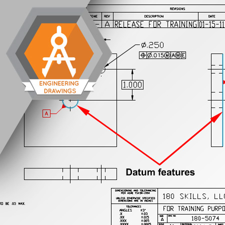
Datums are the foundation that provides a method of aligning geometric tolerance zones to ensure features meet their intended design.
Learning Objectives
- Define a datum
- Define a datum feature
- Identify a datum feature symbol
- Define a simulated datum
- Define a datum reference frame
- Identify a datum target symbol
- >Understand the importance of the order of precedence of datums
Form geometric tolerances are used frequently to control shapes of individual features of parts. Understanding the tolerance zone created by a form geometric tolerance is important for anyone involved in manufacturing.
Learning Objectives
- Identify a tolerance zone for a straightness geometric tolerance
- Identify a tolerance zone for a circularity geometric tolerance
- Identify a tolerance zone for a cylindrical geometric tolerance
- Identify a tolerance zone for a flatness geometric tolerance
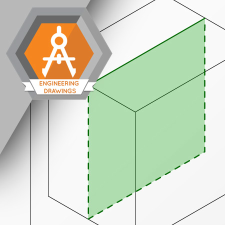
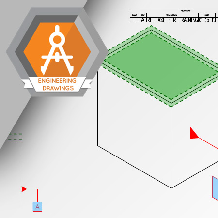
Profile geometric tolerances are used to define the limits of contours of lines and surfaces containing straight lines, arcs, partial cylinders, and even mathematically defined curves.
Learning Objectives
- Define a tolerance zone for a profile of a line
- Define a tolerance zone for the profile of a surface
- Understand unilateral profile tolerancing
- Understand bilateral profile tolerancing
Orientation tolerances control the alignment of features to datum features. Orientation tolerances control the angularity, parallelism, and perpendicularity of features.
Learning Objectives
- Define the tolerance zones for the perpendicularity of a plane or axis
- Define the tolerance zones for the angularity of a plane or axis
- Define the tolerance zone for the parallelism of planes or an axis
- Understand the application of the qualifying notation: “EACH RADIAL ELEMENT”
- Understand the application of a projected tolerance zone
- Understand the characteristic of a thread, or gear, to which a geometric tolerance applies
Runout tolerances are applied to features of rotating parts. These tolerances reduce vibration and uneven wear of the features to which the tolerance is applied.
Learning Objectives
- Define a tolerance zone for a circular runout tolerance
- Define a tolerance zone for a total runout tolerance
- Understand the difference between circular runout and total runout tolerances
- Understand the terms full indicator movement and total indicated reading
Geometric tolerances control the position of axes, center planes, surfaces, and midpoints of features to datum features.
Learning Objectives
- List the three geometric tolerances for location
- Define the tolerance zone for concentricity
- Define the tolerance zone for symmetry
- Define the tolerance zone for the position of a feature at RFS
- Define the tolerance zone for the position of a feature at MMC